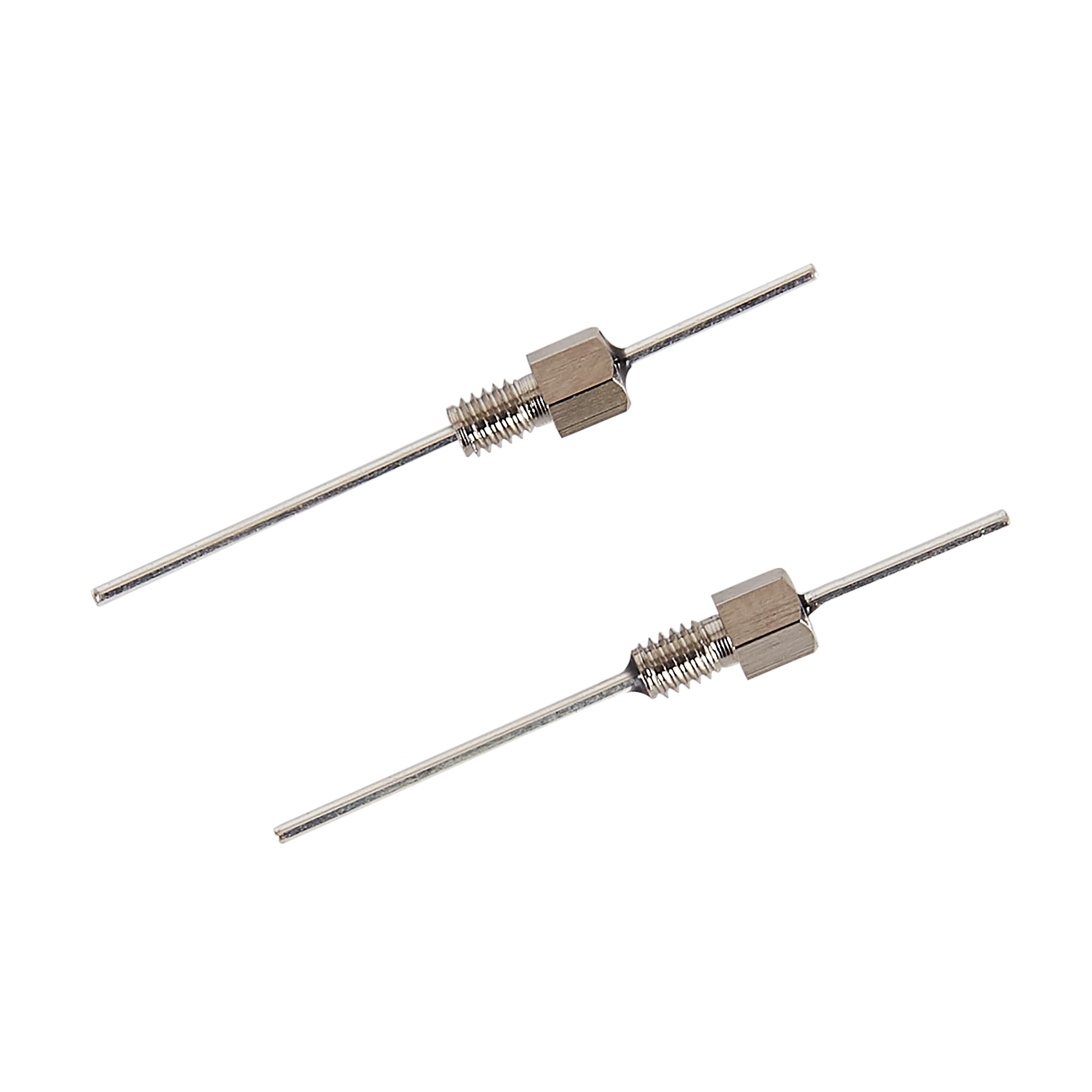
 Screw Type EMI FilterL3325 SeriesL4030 SeriesL5040 SeriesL5060 SeriesL6040 SeriesL6050 SeriesL8050 SeriesL8060 SeriesL9860 SeriesL10080 SeriesL1/4-28UNF-2A SeriesL4-40UNC-2A SeriesL5/16-24UNF-2A SeriesL5/16-32UNEF-2A SeriesL6-32UNC-2A SeriesL8-32UNC-2A SeriesL8-36UNF-2A SeriesL12-28UNF-2A SeriesL12-32UNEF-2A SeriesL140120 Series
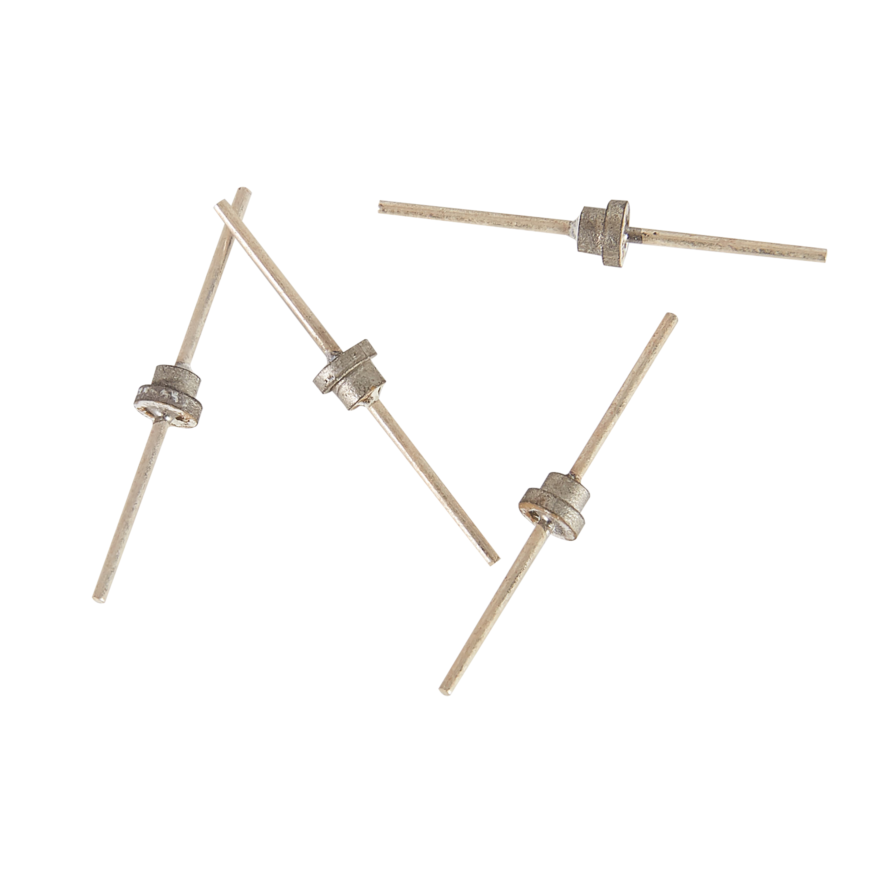 Solder Mount Feed-thru CapacitorH1915 SeriesH2222 SeriesH2416 SeriesH2519 SeriesH2520 SeriesH2618 SeriesH3630 SeriesH3822 SeriesH4033 SeriesH4224 SeriesH4330 SeriesH4532 SeriesH4722 SeriesH4737 SeriesH4743 SeriesH5038 SeriesH5122 SeriesHA4020 SeriesHB2020 SeriesT Series
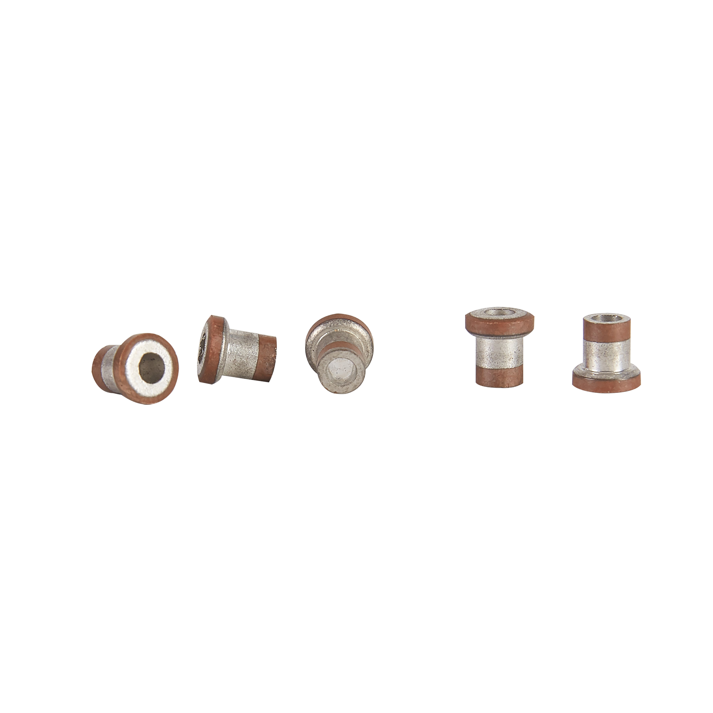 Tubular CapacitorG1915 SeriesG2020 SeriesG2222 SeriesG2416 SeriesG2520 SeriesG2618 SeriesG3822 SeriesG3838 SeriesG4224 SeriesG4330 SeriesG4532 SeriesG4722 SeriesG4737 SeriesG5038 SeriesG6045 Series
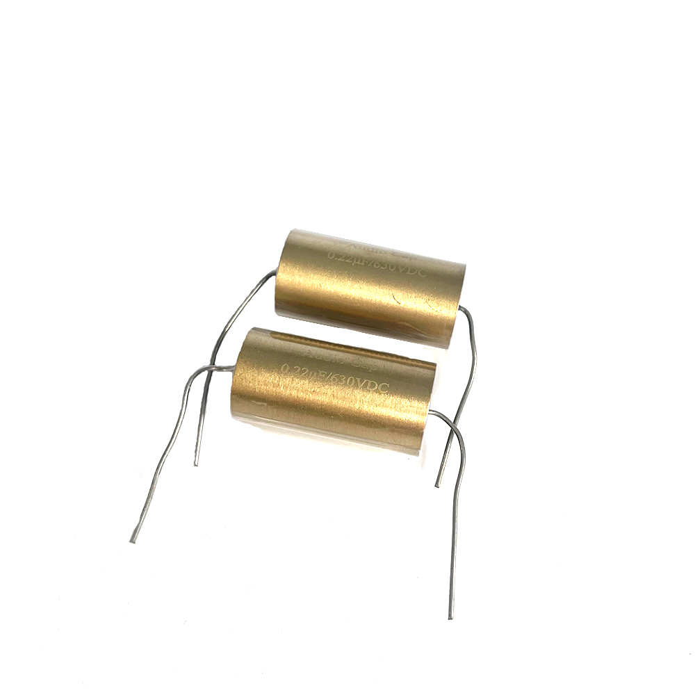 Audio Capacitor
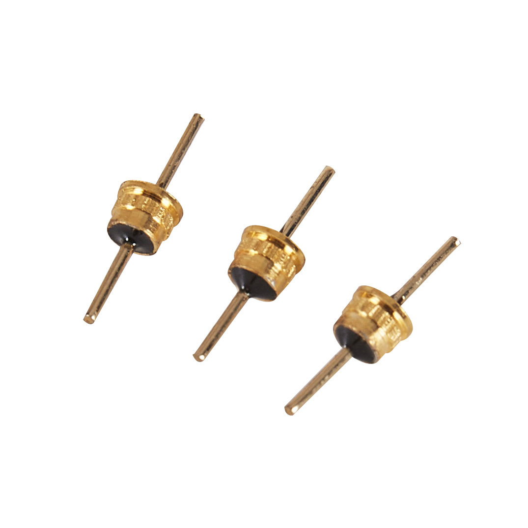 Q4033 Series
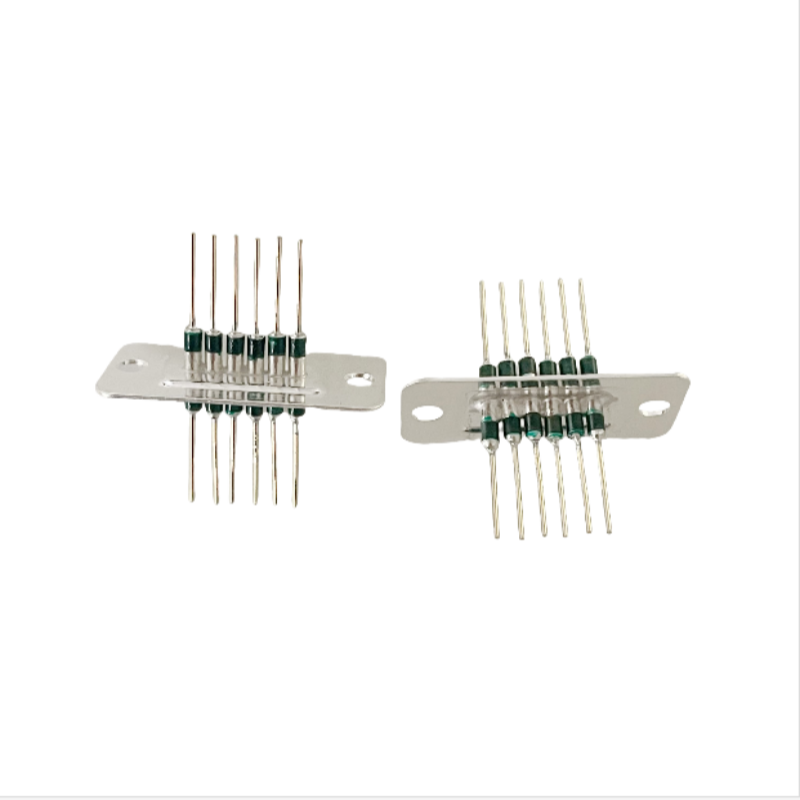 Filtered Array
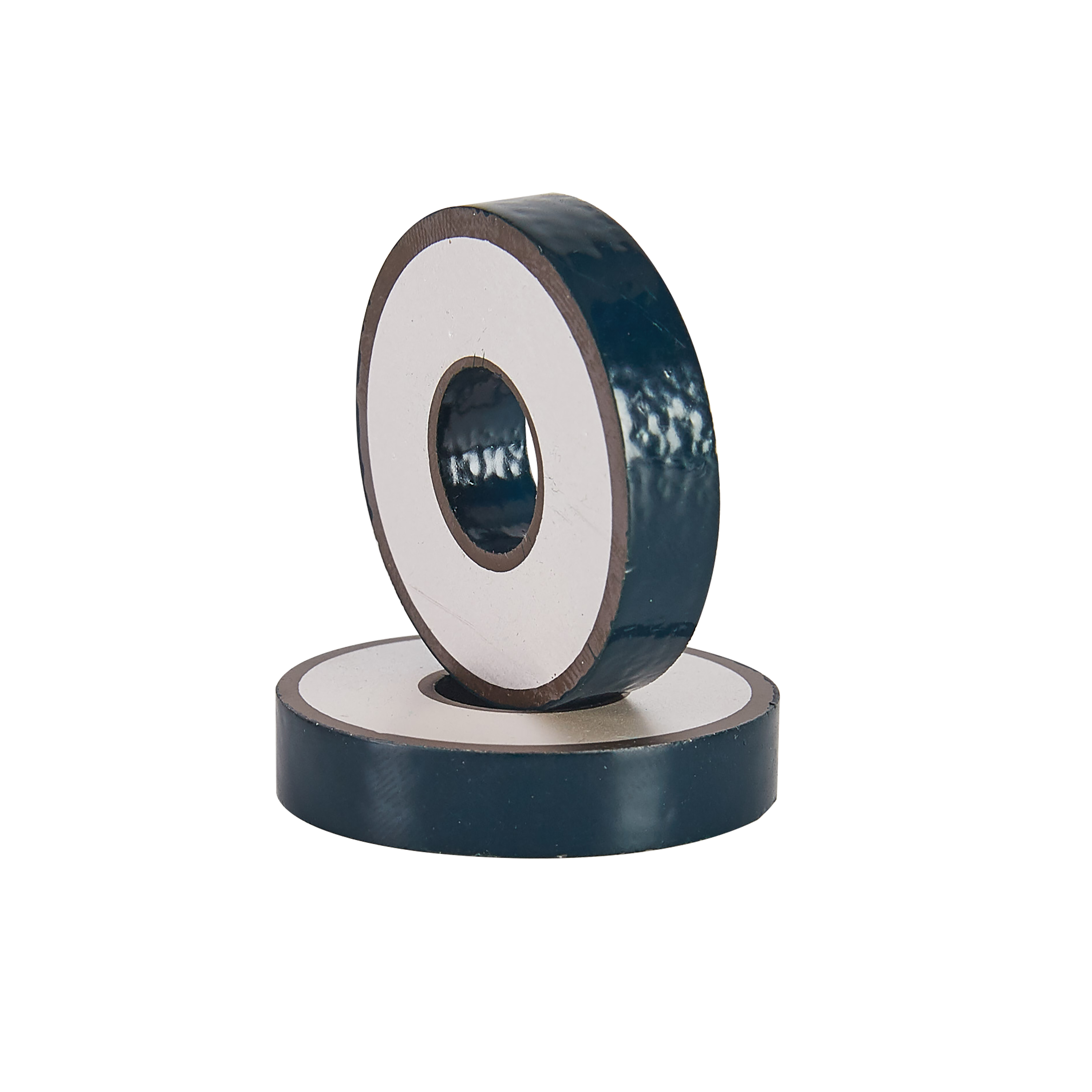 Discoidal Capacitor
 Screw Type EMI Filter
 Solder Mount Feed-thru Capacitor
 Tubular Capacitor
 Audio Capacitor
 Q4033 Series
 Filtered Array
 Discoidal Capacitor

The Difference between Analog Ground and Digital Ground302
Issuing time:2025-06-12 15:43 Simply put, the digital ground is the common reference terminal of the digital circuit part, that is, the reference terminal of the digital voltage signal: The analog ground is the common reference terminal of the analog circuit part, and the voltage reference terminal (zero potential point) of the analog signal. 1. The reason for dividing into digital and analog ground; Due to the fact that digital signals are generally rectangular waves with a large number of harmonics. If the digital ground and analog ground in the circuit board are not separated from the access point, harmonics in the digital signal can easily interfere with the waveform of the analog signal. When analog signals are high-frequency or strong electrical signals, they can also affect the normal operation of digital circuits. Analog circuits involve weak signals, but digital circuit have higher threshold leveles and lower power requirements than analog circuits. In systems with both digital and analog circuits, the noise generated by the digital circuits can affect the analog circuits, causing the small signal indicators of the analog circuit to deteriorate. The solution to overcome this is to separate the analog ground and digital ground. The fundamental reason for the problem is that the resistance of the copper foil on the circuit board cannot be guaranteed to be zero. At the connection point, the digital ground and analog ground are separated in order to minimize the common ground resistance between them. 2. The basic principles of digital and analog processing are as follows: If analog ground and digital ground are directly connected over a large area, it will cause mutual interference. Not short circuiting is not appropriate. For low-frequency analog circuits, in addition to thickening and ground wire, using a single grounding point for each part of the circuit is the best choice to suppress ground wire interference, mainly to prevent mutual interference between components caused by the common impedance of the ground wire. For high-frequency circuits and digital circuit, the inductance effect of the ground wire will have a greater impact, and a single grounding point will cause the actual ground wire to lengthen, resulting in adverse effects. In this case, a combination of separate grounding and single grounding should be adopted. In addition, for high-frequency circuits, it is necessary to consider how to suppress high-frequency radiation noise. The method is to thicken the ground wire as much as possible to reduce the impedance of noise to ground; Full grounding means that all parts except for the printed lines used for transmitting signals are used as ground wire. Do not have useless large-area copper foil. The ground wire should form a loop to prevent the generation of high-frequency radiation noise, but the area enclosed by the loop should not be too large to avoid induced currents when the instrument is in a strong magnetic field. But if it is only a low-frequency circuit, the ground loop should be avoided. It is best to isolate the digital power supply and analog power supply, and arrange the ground wire separately. If there is an A/D, only a single point common ground should be located here. There is not much impact in low frequency, but it is recommended to ground both analog and digital signals. At high frequencies, analog and digital ground can be grounded together through magnetic beads. |
